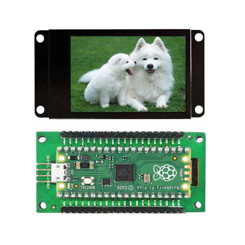
树莓派Pico显示屏2.19寸UART串口屏使用教程
1.接法
1.1通过USB转串口模块与电脑连接
PICO版本:

通用版本:

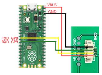
1.2与pico连
pico版本直接插入:
通用版本:
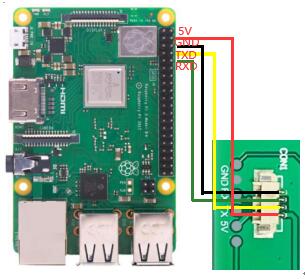
1.3 与树莓派4B连接
PICO版本:
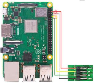
通用版本:
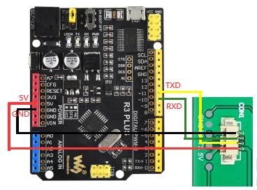
1.4 与arduino
PICO版本:

通用版本:
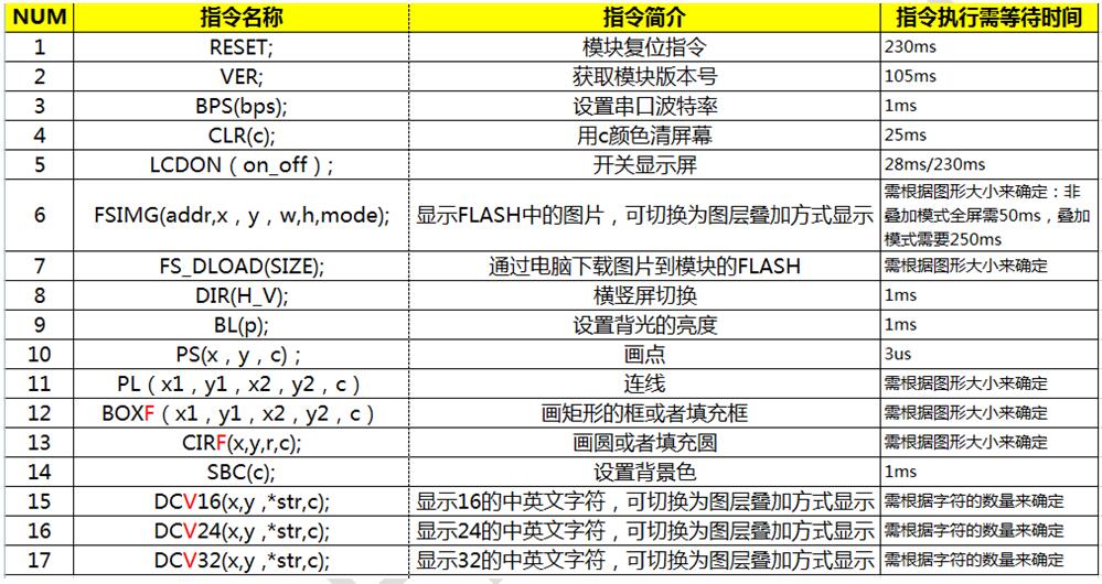
2. 软件指令集
|
指令 |
指令码 |
备注 |
|
模块软件复位指令 |
RESET; |
|
|
通过此指令可以对模块进入软件复位,接收此指令后,模块的外围部件及系统参数将恢复上电的值。 |
||
|
获取模块的版本信息指令 |
VER; |
|
|
通过VER;就可以获取此模块固化的版本信息,并显示在屏幕上面 |
||
|
设置波特率指令 |
BPS(bps); |
系统上电后默认的波特率为115200. |
|
BPS为指令码,括号内为波特率的值。如果要把波特率设置为9600,则 BPS(9600); |
||
|
清屏指令 |
CLR(c); |
注意c的范围是0~15,如果c的值超过15系统将不响应该指令,c值的范围查看下面的颜色列表。 |
|
CLR为指令码,c为清屏使用的背景颜色,具体代码见下面颜色列表。如果要把屏幕填充为黑色,则
CLR(0); |
||
|
LCD控制指令 |
LCDON(on_off); |
On_off的参数只有0或者1,系统忽略其他参数。 |
|
LCDON为指令码,on_off 分别表示启动或者关闭LCD。如LCDON(1);表示启动LCD,LCDON(0);关闭LCD. |
||
|
Flash中的图片显示指令 |
FSIMG(addr,x,y,w,h,mode); |
Mode为1时,图片的白色背景将不会显示,此模式用于图标与背景图片的叠加功能。addr为存储图片的flash开始地址,必须从2097152开始 |
|
FSIMG为指令码,addr为图片存储在flash的地址,x,y为图片要在屏幕上面显示的开始位置,w为图片的宽度,h为图片的高度,mode为图片显示方式:1为透明显示,0为正常显示。如FSIMG
(2097152,0,0,240,400,1);表示从2097152的FLASH地址取出240*400的图片并在0,0的位置上透明显示。 |
||
|
图片下载到FLASH指令 |
FS_DLOAD(SIZE); |
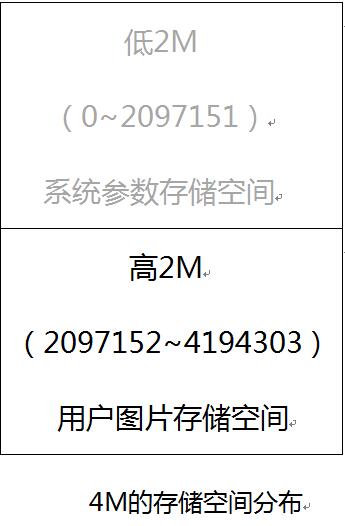
图片是会被下载到FLASH高2M的存储空间,因此从2M(2097152的位置开始存储图片)共2M 此命令支持合并后的图片烧写,不支持单图片文件的烧写。 |
|
FS_DLOAD为指令码,SIZE为要下载的图片的总大小。如FS_DLOAD(192000);表示将192000字节的图片下载到flash中,图片的总大小不能超过2097152字节,如果SIZE的赋值大于2097152字节,系统只识别到2097152字节。 |
||
|
SDIMG 为指令码,x,y为图片要在屏幕显示的开始位置,w,h分别为图片的宽度和高度,‘name’为文件的名字,目前只支持英文名称。SDIMG(0,0,240,400,'6.bin');即表示把SD卡存储的6.bin的文件在模块的0,0的位置显示出来 |
||
|
横竖屏切换指令 |
DIR(H_V); |
系统上电默认为竖屏显示 |
|
如DIR(0);为竖屏。DIR(1);为横屏 |
||
|
设置背光灯的亮度 |
BL(p);其中BL为指令码,p为背光灯的亮度值,调节的范围为:0~255,其中0为全亮显示,255为关闭显示. |
系统上电后,背光的亮度为20 |
|
如BL(4);将背光的亮度设置为4 |
||
|
画点指令 |
PS(x,y,c);
其中PS为指令码,x,y为显示的开始位置,c为点的颜色 |
此指令不适用于大面积的描点,如果真有需求建议内置到模块内部 |
|
如PS(0,0,3);在0,0的位置画一蓝色的点 |
||
|
画线指令 |
PL(x1,y1,x2,y2,c)其中PL为指令码,x1,y1为起点的位置,x2,y2为结束点的位置,c为线的颜色 |
注意c的范围是0~15,如果c的值超过15,系统将会忽略此操作。 |
|
如PL(0,0,50,50,1);表示将0,0 到50,50的两个点用红色连成线 |
||
|
画框指令 |
BOX(x1,y1,x2,y2,c)其中BOX为指令码,x1,y1,为起始点的位置,x2,y2为结束点的位置,c为方框的颜色 |
注意c的范围是0~15,如果c的值超过15,系统将会忽略此操作。 |
|
如BOX (0,0,50,50,1);表示以0,0 为起点到50,50的终止点,画一个红色的框 |
||
|
画填充框指令 |
BOXF(x1,y1,x2,y2,c);其中BOXF为指令码,x1,y1,为起始点的位置,x2,y2为结束点的位置,c为方框的颜色 |
同上 |
|
如BOXF (0,0,50,50,1);表示以0,0 为起点到50,50的终止点,画一个红色的填充框 |
||
|
画圆指令 |
CIR(x,y,r,c);其中CIR为指令码,x,y为圆心的位置,r为圆的半径,c为圆的颜色 |
同上 |
|
如CIR(10,10,3,0);表示以黑色在圆心10,10的位置画一半径为3的黑色的圆 |
||
|
画填充圆指令 |
CIRF(x,y,r,c);其中CIRF为指令码,x,y为圆心的位置,r为圆的半径,c为圆的颜色 |
同上 |
|
如CIRF(10,10,3,0);表示以黑色在圆心10,10的位置画一半径为3的黑色的填充圆 |
||
|
设置背景色指令 |
SBC(c);其中SBC为指令码,c为背景的颜色值,c的范围在0~63之间。 |
同上 |
|
SBC(1);设置背景色为红色 |
||
|
显示16高的字符指令 |
DC16(x,y ,*str,c);其中DC16为指令码,x,y为字符的开始位置,*str为字符的指针,c为字符的颜色 |
同上 |
|
DC16(0,0,'Uart显示屏',1);表示在0,0位置显示’Uart显示屏’字符 |
||
|
显示24高的字符指令 |
DC24(x,y ,*str,c);其中DC24为指令码,x,y为字符的开始位置,*str为字符的指针,c为字符的颜色 |
同上 |
|
DC24(0,0,'Uart显示屏',1);表示在0,0位置显示’Uart显示屏’字符 |
||
|
显示32高的字符指令 |
DC32(x,y ,*str,c);其中DC32为指令码,x,y为字符的开始位置,*str为字符的指针,c为字符的颜色 |
同上 |
|
DC32(0,0,'Uart显示屏',1);表示在0,0位置显示’Uart显示屏’字符 |
||
|
显示16高的带底色的字符指令 |
DCV16(x,y ,*str,c);其中DCV16为指令码,x,y为字符的开始位置,*str为字符的指针,c为字符的颜色 |
底色的设置由SBC指令确定 |
|
DCV16(0,0,'Uart显示屏',1);表示在0,0位置显示’Uart显示屏’字符 |
||
|
显示24高的带底色的字符指令 |
DCV24(x,y ,*str,c);其中DCV24为指令码,x,y为字符的开始位置,*str为字符的指针,c为字符的颜色 |
底色的设置由SBC指令确定 |
|
DCV24(0,0,'Uart显示屏',1);表示在0,0位置显示’Uart显示屏’字符 |
||
|
显示32高的字符带底色的指令 |
DCV32(x,y ,*str,c);其中DCV32为指令码,x,y为字符的开始位置,*str为字符的指针,c为字符的颜色 |
底色的设置由SBC指令确定 |
|
|
DCV32(0,0,'Uart显示屏',1);表示在0,0位置显示’Uart显示屏’字符 |
|
颜色列表
颜色 | 索引c值 |
黑色 | 0 |
红色 | 1 |
绿色 | 2 |
蓝色 | 3 |
黄色 | 4 |
青色 | 5 |
紫色 | 6 |
灰色 | 7 |
浅灰 | 8 |
褐色 | 9 |
墨绿色 | 10 |
深蓝色 | 11 |
深黄色 | 12 |
橙色 | 13 |
浅红 | 14 |
白色 | 15 |
(4)指令需等待时间总结
(5)指令下发时注意事项:
①指令的个数必须严格按照上面列表的内容,并且用括号括起来。
②每条指令的必须使用分号结束,每个操作必须用换行结束。分号字符为:; 换行字符为:’\r\n’
③系统上电后,必须保证主控的串口按照如下的初始化参数进行设置:115200的波特率,无检验位,1个停止位。
3.编程实例:
1.主控(STM32F103RBT6)串口初始化:
void uart_init(u32 bound){
// GPIO_InitTypeDef GPIO_InitStructure;
USART_InitTypeDef
USART_InitStructure;
NVIC_InitTypeDef
NVIC_InitStructure;
RCC_APB2PeriphClockCmd(RCC_APB2Periph_USART1|RCC_APB2Periph_GPIOA|RCC_APB2Periph_AFIO,
ENABLE);//USART1_TX PA.9
GPIO_InitStructure.GPIO_Pin = GPIO_Pin_9;
GPIO_InitStructure.GPIO_Speed = GPIO_Speed_50MHz;
GPIO_InitStructure.GPIO_Mode = GPIO_Mode_AF_PP;
GPIO_Init(GPIOA, &GPIO_InitStructure);
//USART1_RX PA.10
GPIO_InitStructure.GPIO_Pin = GPIO_Pin_10;
GPIO_InitStructure.GPIO_Mode = GPIO_Mode_IN_FLOATING;
GPIO_Init(GPIOA, &GPIO_InitStructure);
//Usart1 NVIC
ÅäÖÃ
NVIC_InitStructure.NVIC_IRQChannel
= USART1_IRQn;
NVIC_InitStructure.NVIC_IRQChannelPreemptionPriority=3
;
NVIC_InitStructure.NVIC_IRQChannelSubPriority
= 3; //
NVIC_InitStructure.NVIC_IRQChannelCmd
= ENABLE;
NVIC_Init(&NVIC_InitStructure);
USART_InitStructure.USART_BaudRate
= bound;//Ò»°ãÉèÖÃΪ9600;
USART_InitStructure.USART_WordLength
= USART_WordLength_8b;
USART_InitStructure.USART_StopBits
= USART_StopBits_1;
USART_InitStructure.USART_Parity
= USART_Parity_No;
USART_InitStructure.USART_HardwareFlowControl
= USART_HardwareFlowControl_None;
USART_InitStructure.USART_Mode
= USART_Mode_Rx | USART_Mode_Tx;
USART_Init(USART1, &USART_InitStructure);
USART_ITConfig(USART1, USART_IT_RXNE, ENABLE);//
USART_Cmd(USART1, ENABLE);
}
void UartSend(char * databuf) //串口发送函数
{
u8
i=0;
while
(1)
{
{
USART_SendData(USART1,
databuf[i]); //
while(USART_GetFlagStatus(USART1,
USART_FLAG_TXE) == RESET){}; //
i++;
}
else return;
}
}
int main(void)
{
SystemInit();//初始化RCC 设置系统主频为72MHZ
delay_init(72); //延时初始化
uart_init(115200); //串口初始化为115200
delay_ms(500);
for(;;)
{
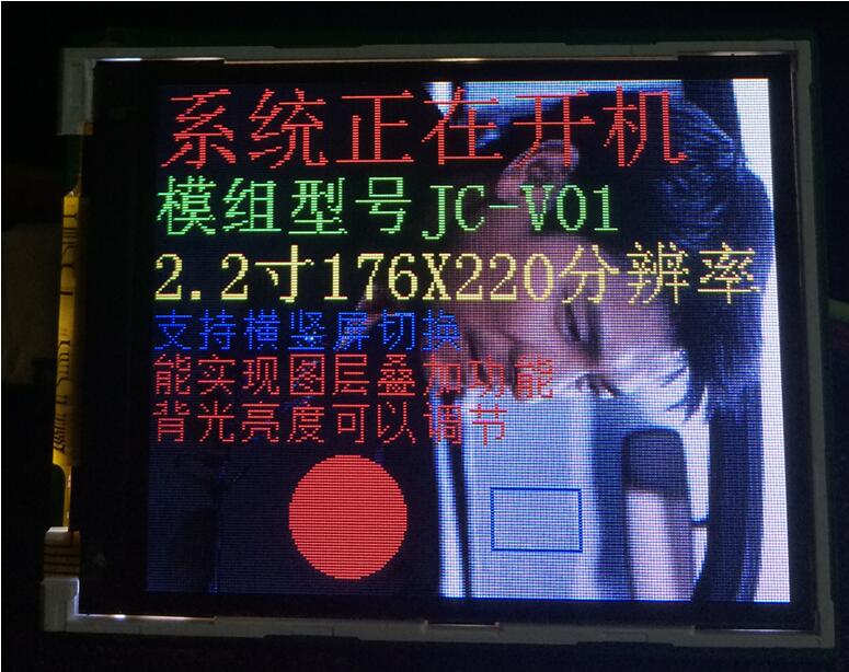
UartSend("SBC(15);DIR(0);FSIMG(2329472,0,0,176,220,0);DIR(1);SBC(10);\r\n");
CheckBusy();
UartSend("DC32(0,0,'系统正在开机',1);\r\n");
CheckBusy();
UartSend("DC24(0,32,'模组型号JC-V01',2);\r\n");
CheckBusy();
UartSend("DC24(0,56,'2.2寸176X220分辨率',4);\r\n");
CheckBusy();
UartSend("DC16(0,80,'支持横竖屏切换',3);\r\n");
CheckBusy();
UartSend("DC16(0,96,'能实现图层叠加功能',1);\r\n");
CheckBusy();
UartSend("DC16(0,112,'背光亮度可以调节',1);\r\n");
CheckBusy();
UartSend("PS(10,10,14);\r\n");
CheckBusy();
UartSend("BOX(120,140,150,160,3);\r\n");
CheckBusy();
CheckBusy();
while(1);
}
}
函数执行的效果:
完整的STM32测试工程请联系我司业务员索取。
编程技巧:
① 如系统的实时性要求很高的话,指令与指令之间可以不需要忙等,主控可以通过侦测模块反馈回来的OK\r\n这三个字符来确定该指令是否执行完,可以提高程序的实时性。
具体可以参考完整的测试代码。
②模块允许串口一次性最多发送24条指令,这样可以大大提高编程的效率,但一定要注意指令的最后一定也要以\r\n为结束符,发送后的等待时间为最后一条指令的等待时间。
2. Pico(Python)
注意:如下的范例分辨率为376x240(下面红色字体需要根据实际修改分辨率和图片地址,蓝色字体要注意不要超过实际范围)代码可在网址根据串口屏幕下载
from machine import UART, Pin
import time
import sys
uart1 = UART(1, baudrate=115200, bits=8, parity=None,
stop=1,tx=Pin(8), rx=Pin(9))
uart0 = UART(0, baudrate=115200, bits=8, parity=None,
stop=1,tx=Pin(0), rx=Pin(1))
txData = u'CLR(0);\r\n'
uart1.write(txData)
time.sleep(0.1)
txData =
b"DIR(1);DC24(20,0,\'spotpear\',1);DC24(20,70,\' UART LCD for
Pico\',2);BOX(120,140,160,180,3);CIRF(70,150,30,4);DELAYMS (500000);DELAYMS
(500000);CLR(0);DIR(1);DELAYMS(400);CLR(6);DELAYMS (400);FSIMG(2097152,0,0,376,240,0);DELAYMS(600);CLR(4);DELAYMS(400);FSIMG(2277632,0,0,376,240,0);;DELAYMS(600);CLR(5);DELAYMS(400);FSIMG(2458112,0,0,376,240,0);\r\n"
uart1.write(txData.decode('unicode'))
time.sleep(0.1)
rxData = bytes()
while uart0.any() > 0:
rxData +=
uart0.read(1)
print(rxData.decode('utf-8'))
3. Raspberry
Pi 3
注意:如下的范例分辨率为220 x176(下面红色字体需要根据实际修改分辨率和图片地址,蓝色字体要注意不要超过实际范围)Raspberry
Pi 2/3代码可在网址下载
#include <stdio.h>
#include <wiringPi.h>
#include <wiringSerial.h>
int main()
{
int fd;
if(wiringPiSetup()
< 0)return 1;
// if((fd =
serialOpen("/dev/ttyAMA0",115200)) < 0)return 1;
if((fd =
serialOpen("/dev/ttyS0",115200)) < 0)return 1;
printf("serial
test start ...\n");
delay(800);
serialPrintf(fd,"RESET;\r\n");//reset the LCD
delay(100);
serialPrintf(fd,"BPS(115200);\r\n");//Set Baud rate
delay(100);
serialPrintf(fd,"CLR(0);\r\n");//Clean
LCD with black color
delay(100);
serialPrintf(fd,"CLR(1);\r\n");//Clean LCD with red color
delay(100);
serialPrintf(fd,"CLR(15);\r\n");//Clean LCD with white color
delay(100);
serialPrintf(fd,"DIR(0);\r\n");//Vertical
display
delay(100);
serialPrintf(fd,"DCV24(0,0,spotpear,0);\r\n");
//display "spotpear" at coordinate(0.0),Font color :0-black;background color :default black
delay(100);
serialPrintf(fd,"SBC(1);\r\n");//set background color red
delay(100);
serialPrintf(fd,"DCV24(0,24,spotpear,0);\r\n");
//display "spotpear" at coordinate(X-0.Y-24)
delay(500);
serialPrintf(fd,"DCV24(0,24,spotpear,3);\r\n");//,Font color :3-;
delay(500);
serialPrintf(fd,"CLR(0);\r\n");//Clean
LCD with black color
delay(500);
serialPrintf(fd,"DIR(1);\r\n");//Horizontal
display
delay(500);
serialPrintf(fd,"DCV16(0,24,spotpear,0);\r\n");
delay(500);
serialPrintf(fd,"DCV32(0,0,spotpear,0);\r\n");
delay(500);
serialPrintf(fd,"CIRF(40,80,20,3);\r\n");//filling circle
coordinate(X-40.Y-80,r-20,color-3)
delay(100);
serialPrintf(fd,"CIR(70,150,20,1);\r\n");//circle
coordinate(X-70.Y-150,r-20,color-1)
delay(500);
serialPrintf(fd,"BOXF(70,150,90,170,3);\r\n");//rectangle coordinate
delay(500);
serialPrintf(fd,"BOX(40,80,70,110,3);\r\n");//rectangle coordinate
delay(500);
serialPrintf(fd,"PL(0,0,220,176,6);\r\n");//line: color-6,
delay(500);
serialPrintf(fd,"PS(110,110,4);\r\n");//line: color-6,
delay(1000);
serialPrintf(fd,"DIR(0);\r\n");//Vertical display
delay(100);
serialPrintf(fd,"FSIMG(2097152,0,0,176,220,0);\r\n");
//load picture-1 from LCD(picture loaded by computer UART software in advance)
delay(500);
serialPrintf(fd,"FSIMG(2174592,0,0,176,220,0);\r\n");//load
picture-2 from LCD
delay(500);
serialPrintf(fd,"FSIMG(2252032,0,0,176,220,0);\r\n");
delay(500);
serialPrintf(fd,"BL(1023);\r\n");////Backlight
ightness:1024-open display
delay(1000);
serialPrintf(fd,"BL(0);\r\n");//Backlight ightness:0-stop
display
delay(300);
//
serialPrintf(fd,"RESET;\r\n");//reset*/
//
delay(300);
serialPrintf(fd,"DCV24(0,0,spotpear,0);\r\n");
delay(300);
//while(1)
//{
// serialPutchar(fd,serialGetchar(fd));
//}
serialClose(fd);
return 0;
}
4. Arduino
注意:如下的范例分辨率为220 x176(下面红色字体需要根据实际修改分辨率和图片地址,蓝色字体要注意不要超过实际范围)
UARTLCD22-1
/*
Software serial multple serial test
Receives from the hardware serial, sends to
software serial.
Receives from software serial, sends to
hardware serial.
The circuit:
* RX is digital pin 10 (connect to TX of other
device)
* TX is digital pin 11 (connect to RX of other
device)
Note:
Not all pins on the Mega and Mega 2560 support
change interrupts,
so only the following can be used for RX:
10, 11, 12, 13, 50, 51, 52, 53, 62, 63, 64,
65, 66, 67, 68, 69
Not all pins on the Leonardo support change
interrupts,
so only the following can be used for RX:
8, 9, 10, 11, 14 (MISO), 15 (SCK), 16 (MOSI).
created back in the mists of time
modified 25 May 2012
by Tom Igoe
based on Mikal Hart's example
This example code is in the public domain.
*/
#include
<SoftwareSerial.h>
SoftwareSerial
mySerial(10, 11); // RX, TX
void
setup()
{
mySerial.begin(115200);
delay(800);
mySerial.println("RESET;\r\n");
delay(100);
mySerial.println("BPS(115200);\r\n");
delay(100);
mySerial.println("CLR(1);\r\n");
delay(500);
mySerial.println("CLR(15);\r\n");
delay(500);
mySerial.println("DIR(0);\r\n");
delay(100);
mySerial.println("DCV24(0,0,spotpear,0);\r\n");
delay(100);
mySerial.println("SBC(1);\r\n");
delay(100);
mySerial.println("DCV24(0,24,spotpear,0);\r\n");
delay(300);
mySerial.println("DCV24(0,24,spotpear,3);\r\n");
delay(300);
mySerial.println("CLR(0);\r\n");
delay(300);
mySerial.println("FSIMG(2097152,0,0,176,220,0);\r\n");
delay(300);
mySerial.println("FSIMG(2174592,0,0,176,220,0);\r\n");
delay(300);
mySerial.println("FSIMG(2252032,0,0,176,220,0);\r\n");
delay(300);
mySerial.println("BL(1023);\r\n");
delay(1000);
mySerial.println("BL(0);\r\n");
delay(1000);
}
void
loop() // run over and over
{
delay(300);
}
UARTLCD22-2
/*
Software serial multple serial test
Receives from the hardware serial, sends to
software serial.
Receives from software serial, sends to
hardware serial.
The circuit:
* RX is digital pin 10 (connect to TX of other
device)
* TX is digital pin 11 (connect to RX of other
device)
Note:
Not all pins on the Mega and Mega 2560 support
change interrupts,
so only the following can be used for RX:
10, 11, 12, 13, 50, 51, 52, 53, 62, 63, 64,
65, 66, 67, 68, 69
Not all pins on the Leonardo support change
interrupts,
so only the following can be used for RX:
8, 9, 10, 11, 14 (MISO), 15 (SCK), 16 (MOSI).
created back in the mists of time
modified 25 May 2012
by Tom Igoe
based on Mikal Hart's example
This example code is in the public domain.
*/
#include
<SoftwareSerial.h>
SoftwareSerial
mySerial(10, 11); // RX, TX
void
setup()
{
mySerial.begin(115200);
delay(800);
mySerial.println("RESET;\r\n");
delay(300);
mySerial.println("DIR(1);\r\n");
delay(500);
mySerial.println("CLR(0);\r\n");
delay(500);
mySerial.println("DCV16(0,24,spotpear,0);\r\n");
delay(300);
mySerial.println("DCV32(0,0,spotpear,0);\r\n");
delay(300);
mySerial.println("CIRF(40,80,20,3);\r\n");
delay(300);
mySerial.println("CIR(70,150,20,1);\r\n");
delay(300);
mySerial.println("BOXF(70,150,90,170,3);\r\n");
delay(300);
mySerial.println("BOX(40,80,70,110,3);\r\n");
delay(300);
mySerial.println("PL(0,0,220,176,6);\r\n");
delay(300);
mySerial.println("PS(110,110,4);\r\n");
delay(300);
}
void
loop() // run over and over
{
delay(1000);
}
5.图片存储及读取操作说明
(注意:如下的范例为240x400的图片,此模块为176x220,实际操作时记得调整这个参数)
(1) 如用户需要存储的图片总大小小于2M时,可以把图片存入到模块为用户开辟的2M图片存储空间中(即FLASH的高2M空间)。
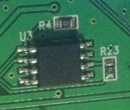
板子的FLASH芯片
(2)要下载的图片文件的获取方法:
①从美工设计部门获取bmp后缀的图片素材(此BMP为24位格式),如果素材是其他格式的图片(例如jpeg或者png),就必须另存为BMP格式。
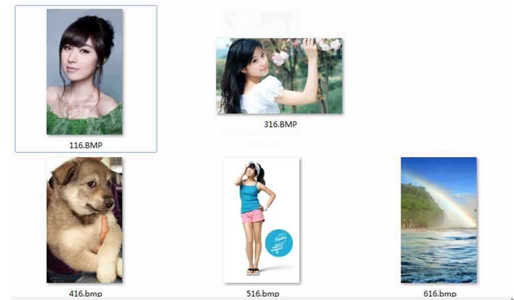
如上均为要显示的bmp格式的素材图片
②打开Image2Lcd.exe取模软件,导入图片,注意红色框中的设置一定要和图片中的一致,蓝色框的分辨率需要根据具体的图片大小来确定。

导入图片后的软件界面
③点击软件左上方的保存按键,即可以保存为bin文件,使用同样的方法,将需要的图片都保存为bin文件。
④打开EzOSD.exe文件,选中“Merge”,选择左上方的路径并从右下方双击选中刚刚保存的bin文件,选中的文件会显示在右方的列表中。
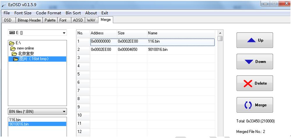
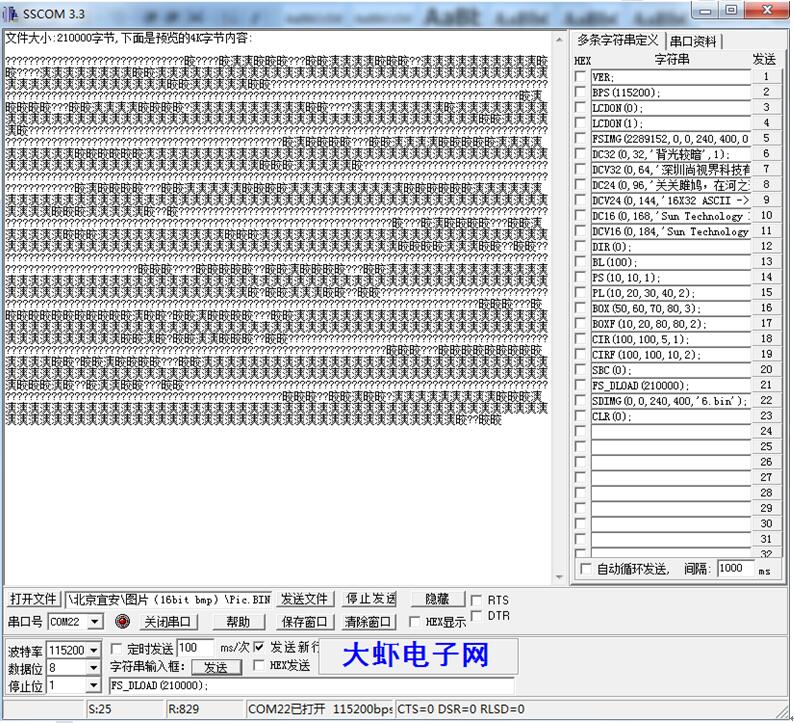
注意,此时我只选择了2个bin文件,第一张为240x400的全屏图片,第二张为90x100的窗口图片,两个图片的总大小为:210000字节
⑤点击右下方的Merge按钮,合并并保存为Pic.bin
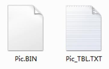
注意 Pic_TBL.TXT为图片合并的信息(包括偏移地址和大小),如下图

此时,要烧录的Pic.bin就已经制作完成。
(3)将Pic.bin下载到模块中(使用串口终端下载)
①打开串口终端SSCOM 3.3 exe,将模块和电脑的串口连接好,设置好终端的波特率等参数。
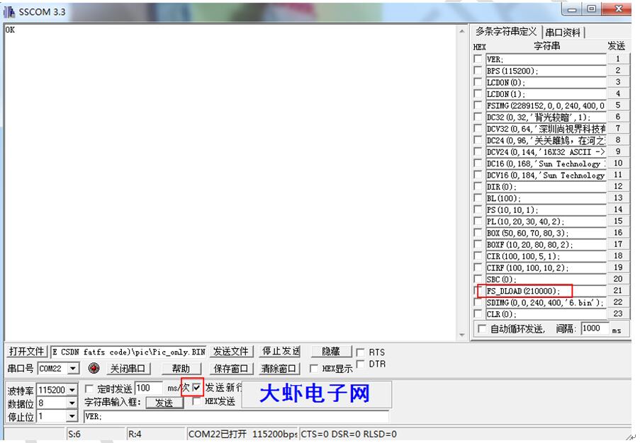
②注意要选择发送新行复选框,此时用115200的波特率向模块发送FS_DLOAD(210000);命令,接收命令后模块会向终端返回FLASH正在擦除的信息,等待FLASH擦除完成。
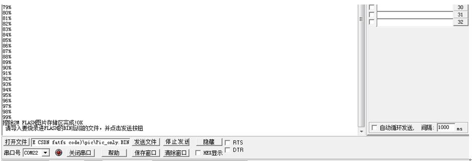
③擦除完成后,通过‘’打开文件‘’按钮即可导入刚刚生成的Pic.bin文件。
文件已经导入,点击‘’发送文件‘’按钮
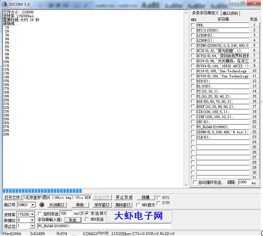
④等待烧录完成。
(5) 显示下载到FLASH中的图片
①FSIMG(2097152,0,0,240,400,0);
在模块的0,0处开始显示显示第一张图片,其中2097152为图片存储的开始地址.,图片的大小为240*400。
②FSIMG(2097152+192000,0,0,90,100,0);
显示第二张图片,其中偏移地址+192000,即表示第二张图片是紧接着第一张图片的位置存取。