树莓派1.14寸 1.3寸显示屏使用教程
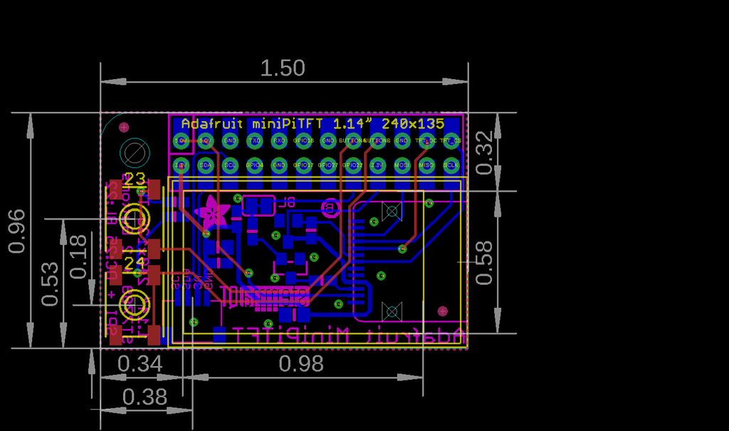
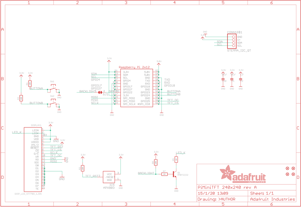
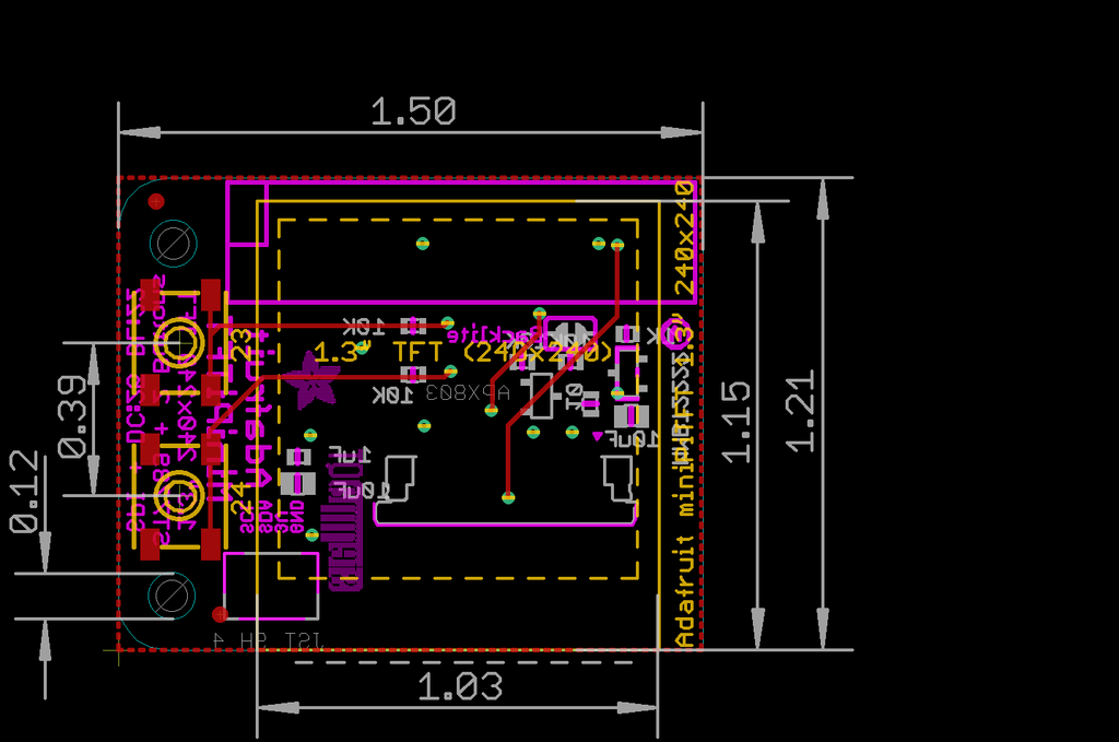
Mini Pi TFT的1.3英寸和1.14英寸版本都具有相同的2x12连接器和引脚排列。
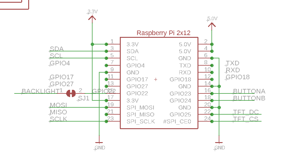
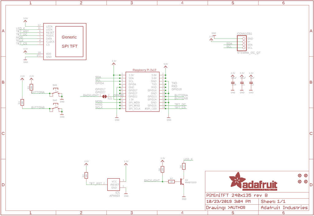
Mini Pi TFT连接到Pi 2x 20集管接口上的“顶部”2x12集管。它使用以下引脚:
- 5.0V - 连接到显示器背光
- 3.3V - 连接到显示电源和STEMMA QT / Qwiic连接器
- GND - 万物之地
- SDA & SCL - I2C数据。不被按钮或显示器使用
- GPIO22 - 用于打开和关闭背光。如果你永远不想关掉背光,剪下底部的小跳线,释放GPIO22
- GPIO23 & GPIO24 - 连接到两个前按钮。这些引脚的10K上拉电压为3.3V,因此当按下按钮时,这些引脚上的电压会很低
- SCK, MOSI, CE0 & GPIO25 - 这些是显示控制引脚。请注意,即使是SPI引脚,MISO也没有连接,因为您无法从显示器上读取。
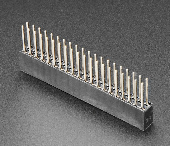
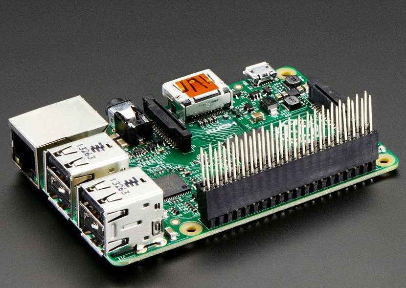
未使用:GPIO4、GPIO17、GPIO18、GPIO27 如果您使用的是240x135 1.14英寸(小矩形)Mini Pi TFT,如果您使用堆叠头,您可以将其他硬件连接到这些引脚上的Pi-它将通过Mini PiTFT上的2x12连接器。这在1.3英寸上是行不通的,因为孔不会穿过印刷电路板
1.14寸/1.3寸显示屏内核模块安装:
240x135Mini Pi TFT太小了,这不是小TFT默认支持的分辨率。这项技术将更新你的内核到最新的,如果你升级你的树莓派来代替内核,你需要重新运行指令!如果您从Pi Zero / Pi 2 / Pi 3 / Pi 4更改,您还需要重新运行,因为这些都使用不同的内核类型。
有两种方法可以使用240x135显示屏。
要意识到你一次只能选择做一种方式。如果你选择难的方式,它会安装内核驱动程序,这将阻止你以简单的方式做这件事。
简单的方法是使用“pure Python 3”和Pillow库从Python内部绘制到显示器。这对于显示你自己设计的文本、统计数据、图像等非常有用。如果您想这样做,请跳过此页面,转到Python安装/使用页面
困难的方法是安装一个内核模块来增加对薄膜晶体管显示器的支持,这将使控制台出现在显示器上。这很聪明,因为你可以让任何程序打印文本或绘制到帧缓冲区(或者说,用pygame),Linux会为你显示它。如果您不需要控制台或直接帧缓冲区访问,请考虑使用“pure Python”技术,因为它不那么微妙。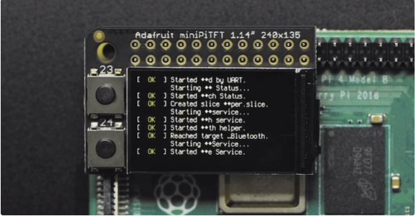
您不会得到图形用户界面/LXDE显示,这只是为了文本控制台的使用。显示器对LXDE来说太小了
准备树莓派!
在你开始之前,让你的树莓派完全更新和升级是一个好主意。我们假设你烧了一张SD卡,可以登录到控制台安装东西。
运行
- sudo apt update -y
- sudo apt-get update -y
- sudo apt-get upgrade -y
完全更新和升级你的树莓派!

在此之后,完成运行 sudo关闭-现在 安全关闭树莓派。拔下电源并连接mini Pi TFT。注意插脚插入到第一个2x12插头中!圆角和安装孔应对齐。

给Pi加电并重新登录。Pi TFT应该点亮,但屏幕上什么也没有。
在终端运行以下内容
- cd ~
- sudo pip3 install --upgrade adafruit-python-shell click==7.0
- sudo apt-get install -y git
- git clone https://github.com/adafruit/Raspberry-Pi-Installer-Scripts.git
- cd Raspberry-Pi-Installer-Scripts
- sudo python3 adafruit-pitft.py --display=st7789_240x135 --rotation=90 --install-type=console

当你被要求重启时,重启!
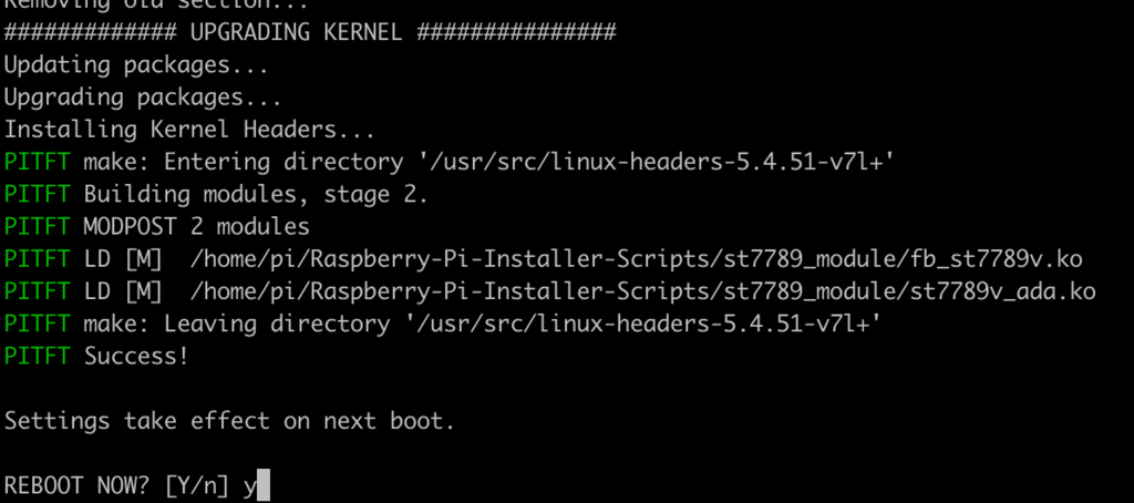
就这样!现在,您将拥有一个带有控制台显示的mini Pi TFT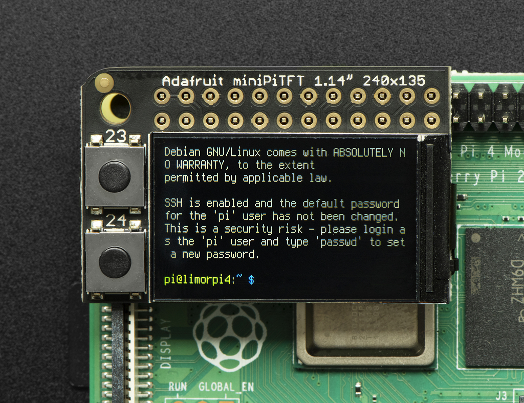
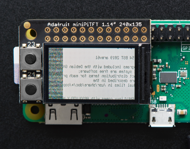
如果你曾经得到这样的显示,这意味着你的内核改变了——要么是因为升级/更新,要么是因为你换了树莓派板。解决方法就是简单的重新运行上面的脚本!
Python 安装程序
从240x135迷你pift到320x480,您可以在任何pift上使用这种技术。它没有内核模块支持版本快,但是不管什么内核/操作系统/版本/等等,它都可以工作,所以困难要小得多
连接
使用Python和 Adafruit CircuitPython RGB Display 模块很容易使用显示中断。该模块允许您轻松编写Python代码来控制显示。
由于Pi TFT是预先组装好的,您只需将其放在GPIO引脚上。
因为有几十台你可以使用的电脑/主板,我们将展示树莓派的布线。对于其他平台,请访问Linux上的电路Python指南,了解您的平台是否受支持。
将如下所示的显示器连接到您的树莓派上。
请注意,这不是一个内核驱动程序,让你的控制台出现在薄膜晶体管。但是,当你不能安装一个fbtft驱动程序,想纯粹从‘用户Python’代码使用tft的时候,这个就方便了!
您只能将此技术用于支持硬件SPI的Linux/计算机设备,并且并非所有单板计算机都有SPI设备,因此在继续之前请进行检查
对于1.14 :
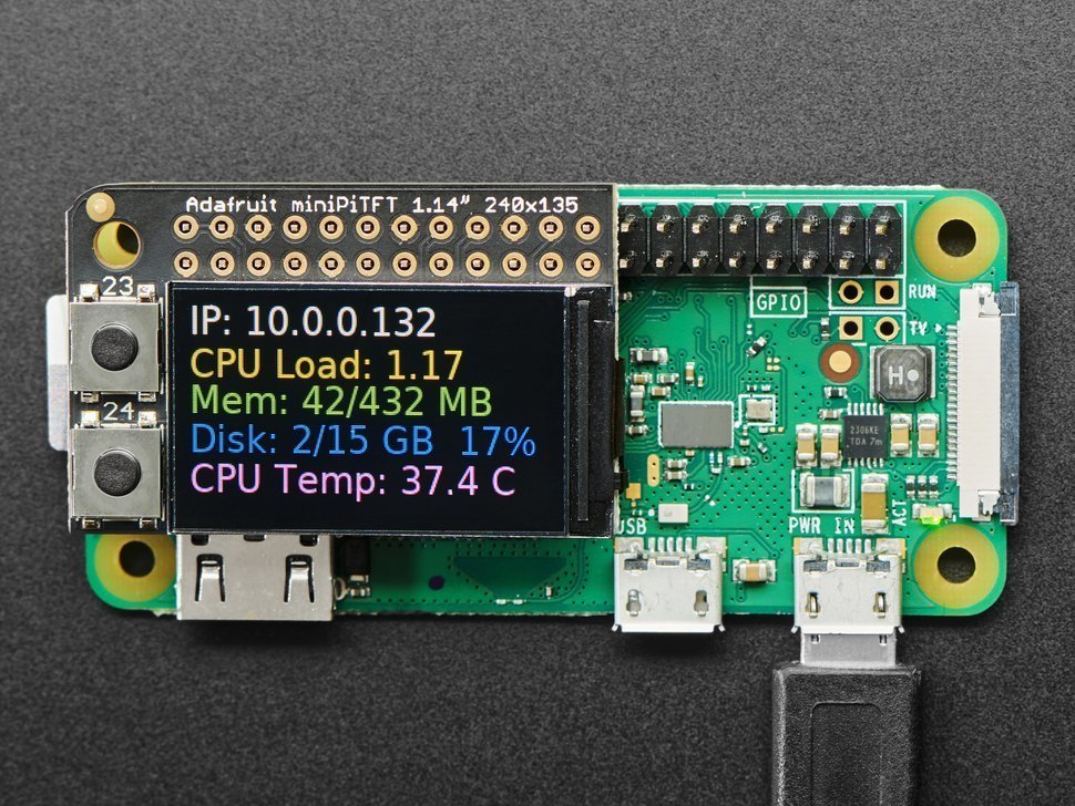
对于1.3:
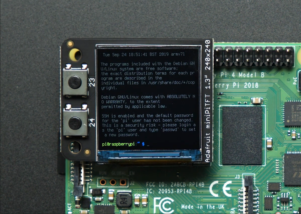
设置
您需要安装Adapour _ Blinka库,该库提供Python中的电路Python支持。这可能还需要在您的平台上启用SPI,并验证您正在运行Python 3。由于每个平台都有一点不同,并且Linux经常变化,请访问Linux上的电路Python指南,准备好您的计算机!
如果您已经安装了内核模块,您将需要在继续之前通过编辑/boot/config.txt文件来删除它。
RGB显示库的Python安装
完成后,从命令行运行以下命令:
sudo pip3 install adafruit-circuitpython-rgb-displaysudo pip3 install --upgrade --force-reinstall spidev
sudo apt-get install python3-pip
Pillow Library
我们还需要PIL,Python图像库,允许图形和使用自定义字体的文本。PIL依赖于几个系统库,因此通过包管理器安装是引入所有内容的最简单方法:
sudo apt-get install python3-pil
NumPy Library
最近对RGB_Display库的改进利用了NumPy来提高速度。这可以通过以下命令安装:
sudo apt-get install python3-numpy
就是这样。你应该准备好出发了。
该按钮测试演示将进行测试,以确保一切设置正确。继续,将文件保存到您主目录中的树莓Pi中,格式为rgb_display_minipitfttest.py.
- import digitalio
- import board
- from adafruit_rgb_display.rgb import color565
- import adafruit_rgb_display.st7789 as st7789
- # Configuration for CS and DC pins for Raspberry Pi
- cs_pin = digitalio.DigitalInOut(board.CE0)
- dc_pin = digitalio.DigitalInOut(board.D25)
- reset_pin = None
- BAUDRATE = 64000000 # The pi can be very fast!
- # Create the ST7789 display:
- display = st7789.ST7789(
- board.SPI(),
- cs=cs_pin,
- dc=dc_pin,
- rst=reset_pin,
- baudrate=BAUDRATE,
- width=135,
- height=240,
- x_offset=53,
- y_offset=40,
- )
- backlight = digitalio.DigitalInOut(board.D22)
- backlight.switch_to_output()
- backlight.value = True
- buttonA = digitalio.DigitalInOut(board.D23)
- buttonB = digitalio.DigitalInOut(board.D24)
- buttonA.switch_to_input()
- buttonB.switch_to_input()
- # Main loop:
- while True:
- if buttonA.value and buttonB.value:
- backlight.value = False # turn off backlight
- else:
- backlight.value = True # turn on backlight
- if buttonB.value and not buttonA.value: # just button A pressed
- display.fill(color565(255, 0, 0)) # red
- if buttonA.value and not buttonB.value: # just button B pressed
- display.fill(color565(0, 0, 255)) # blue
- if not buttonA.value and not buttonB.value: # none pressed
- display.fill(color565(0, 255, 0)) # green
继续使用以下命令运行它:
sudo python3 rgb_display_minipitfttest.py
一旦它运行,按下按钮。顶部的按钮应该使显示屏亮起红色,底部的蓝色,同时按下这两个按钮应该使其变为绿色。
Python统计示例
如果您之前已经安装了pitft easy安装程序的内核驱动程序,那么为了运行这个示例,您需要首先删除它
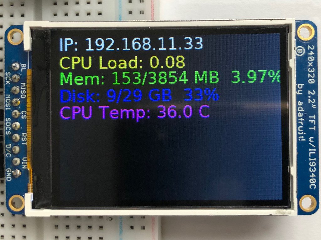
我们还可以显示一些关于您的Pi的统计数据,如IP地址、资源使用情况,甚至CPU温度。首先将下面的代码保存在你的树莓皮的主目录中。
- # -*- coding: utf-8 -*-
- import time
- import subprocess
- import digitalio
- import board
- from PIL import Image, ImageDraw, ImageFont
- import adafruit_rgb_display.st7789 as st7789
- # Configuration for CS and DC pins (these are FeatherWing defaults on M0/M4):
- cs_pin = digitalio.DigitalInOut(board.CE0)
- dc_pin = digitalio.DigitalInOut(board.D25)
- reset_pin = None
- # Config for display baudrate (default max is 24mhz):
- BAUDRATE = 64000000
- # Setup SPI bus using hardware SPI:
- spi = board.SPI()
- # Create the ST7789 display:
- disp = st7789.ST7789(
- spi,
- cs=cs_pin,
- dc=dc_pin,
- rst=reset_pin,
- baudrate=BAUDRATE,
- width=135,
- height=240,
- x_offset=53,
- y_offset=40,
- )
- # Create blank image for drawing.
- # Make sure to create image with mode 'RGB' for full color.
- height = disp.width # we swap height/width to rotate it to landscape!
- width = disp.height
- image = Image.new("RGB", (width, height))
- rotation = 90
- # Get drawing object to draw on image.
- draw = ImageDraw.Draw(image)
- # Draw a black filled box to clear the image.
- draw.rectangle((0, 0, width, height), outline=0, fill=(0, 0, 0))
- disp.image(image, rotation)
- # Draw some shapes.
- # First define some constants to allow easy resizing of shapes.
- padding = -2
- top = padding
- bottom = height - padding
- # Move left to right keeping track of the current x position for drawing shapes.
- x = 0
- # Alternatively load a TTF font. Make sure the .ttf font file is in the
- # same directory as the python script!
- # Some other nice fonts to try: http://www.dafont.com/bitmap.php
- font = ImageFont.truetype("/usr/share/fonts/truetype/dejavu/DejaVuSans.ttf", 24)
- # Turn on the backlight
- backlight = digitalio.DigitalInOut(board.D22)
- backlight.switch_to_output()
- backlight.value = True
- while True:
- # Draw a black filled box to clear the image.
- draw.rectangle((0, 0, width, height), outline=0, fill=0)
- # Shell scripts for system monitoring from here:
- # https://unix.stackexchange.com/questions/119126/command-to-display-memory-usage-disk-usage-and-cpu-load
- cmd = "hostname -I | cut -d' ' -f1"
- IP = "IP: " + subprocess.check_output(cmd, shell=True).decode("utf-8")
- cmd = "top -bn1 | grep load | awk '{printf \"CPU Load: %.2f\", $(NF-2)}'"
- CPU = subprocess.check_output(cmd, shell=True).decode("utf-8")
- cmd = "free -m | awk 'NR==2{printf \"Mem: %s/%s MB %.2f%%\", $3,$2,$3*100/$2 }'"
- MemUsage = subprocess.check_output(cmd, shell=True).decode("utf-8")
- cmd = 'df -h | awk \'$NF=="/"{printf "Disk: %d/%d GB %s", $3,$2,$5}\''
- Disk = subprocess.check_output(cmd, shell=True).decode("utf-8")
- cmd = "cat /sys/class/thermal/thermal_zone0/temp | awk '{printf \"CPU Temp: %.1f C\", $(NF-0) / 1000}'" # pylint: disable=line-too-long
- Temp = subprocess.check_output(cmd, shell=True).decode("utf-8")
- # Write four lines of text.
- y = top
- draw.text((x, y), IP, font=font, fill="#FFFFFF")
- y += font.getsize(IP)[1]
- draw.text((x, y), CPU, font=font, fill="#FFFF00")
- y += font.getsize(CPU)[1]
- draw.text((x, y), MemUsage, font=font, fill="#00FF00")
- y += font.getsize(MemUsage)[1]
- draw.text((x, y), Disk, font=font, fill="#0000FF")
- y += font.getsize(Disk)[1]
- draw.text((x, y), Temp, font=font, fill="#FF00FF")
- # Display image.
- disp.image(image, rotation)
- time.sleep(0.1)
通过键入以下内容继续运行脚本:
python3 stats.py
它应该显示一些系统信息。

1.3英寸显示屏的改进
为了让stats.py示例在1.3英寸薄膜晶体管显示器上正确显示,您需要根据显示器的不同几何形状进行一些更改。您需要调整的参数是高度、x_offset、y_offset和旋转。
height = 240x_offset = 0y_offset = 80rotation = 180
替换它们最简单的方法可能是复制下面的代码块,并在上面的代码中替换它。
- # Create the ST7789 display:
- disp = st7789.ST7789(
- spi,
- cs=cs_pin,
- dc=dc_pin,
- rst=reset_pin,
- baudrate=BAUDRATE,
- width=240,
- height=240,
- x_offset=0,
- y_offset=80,
- )
- # Create blank image for drawing.
- # Make sure to create image with mode 'RGB' for full color.
- height = disp.width # we swap height/width to rotate it to landscape!
- width = disp.height
- image = Image.new("RGB", (width, height))
- rotation = 180
启动时运行统计
你可以很容易地做到这一点,所以这个方便的程序运行,每次你启动你的树莓派。
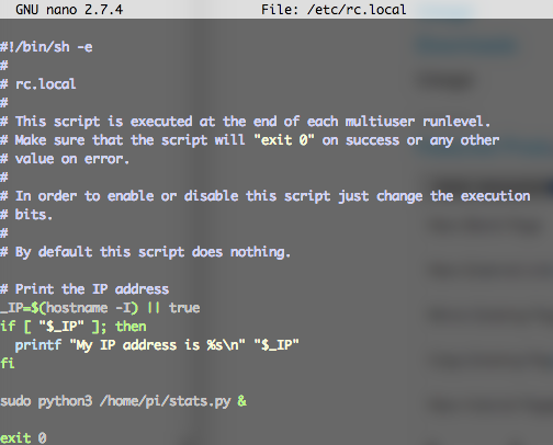
最快/最简单的方法是放入/etc/rc.local
运行sudo nano /etc/rc.local并添加行
sudo python3 /home/pi/stats.py &
就在0号出口前 然后保存并退出。重启以验证屏幕在启动时出现!
启动时统计故障排除
为了在树莓派上正常安装Blinka,我们让您安装没有sudo关键字的东西,这将在本地安装库。但是,要让脚本在启动时运行,您需要在更大的系统范围内提供库。您可以通过运行以下命令来测试这一点,并查看统计数据是否出现:
sudo python3 /home/pi/stats.py
如果您有任何错误,大多数都可以通过运行以下命令来修复:
sudo pip3 install --upgrade adafruit-blinka adafruit-circuitpython-rgb-display spidev
一旦你能让它启动,继续按下控制+C并重新启动系统。现在应该上来了。
有时Pi启动太快,所以您可能还需要在/etc/rc.local.中添加的命令之前添加 sleep 10
Python 用法
如果您之前已经安装了带有PiTFT简易安装程序的内核驱动程序,您将需要首先删除它才能运行此示例。
现在您已经设置好了一切,我们将查看三个不同的示例。首先,我们将看一下自动缩放和裁剪图像,然后将其居中显示。
打开背光
在一些显示器上,背光由单独的引脚控制,例如带操纵杆的1.3英寸薄膜晶体管阀盖。在这种显示器上,运行下面的代码可能会导致显示器保持黑色。要打开背光,您需要添加一小段代码。如果您的背光引脚编号不同,请务必在代码中进行更改:
- # Turn on the Backlight
- backlight = DigitalInOut(board.D26)
- backlight.switch_to_output()
- backlight.value = True
显示图像
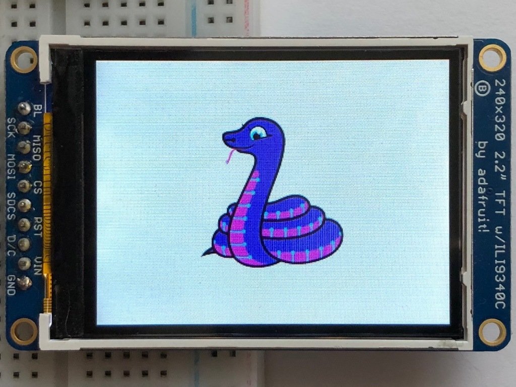
下面是这个例子的完整代码。我们将一节一节地讲解,以帮助您更好地理解正在发生的事情。先来下载一张Blinka的图片。该图像有足够的边框,可以根据不同的显示大小和比例调整大小和裁剪,以保持良好的外观。

请确保将其保存为blinka.jpg,并将其放在与脚本相同的文件夹中。下面是我们将要加载到树莓派上的代码。我们将讨论有趣的部分。
- """
- Be sure to check the learn guides for more usage information.
- This example is for use on (Linux) computers that are using CPython with
- Adafruit Blinka to support CircuitPython libraries. CircuitPython does
- not support PIL/pillow (python imaging library)!
- Author(s): Melissa LeBlanc-Williams for Adafruit Industries
- """
- import digitalio
- import board
- from PIL import Image, ImageDraw
- import adafruit_rgb_display.ili9341 as ili9341
- import adafruit_rgb_display.st7789 as st7789 # pylint: disable=unused-import
- import adafruit_rgb_display.hx8357 as hx8357 # pylint: disable=unused-import
- import adafruit_rgb_display.st7735 as st7735 # pylint: disable=unused-import
- import adafruit_rgb_display.ssd1351 as ssd1351 # pylint: disable=unused-import
- import adafruit_rgb_display.ssd1331 as ssd1331 # pylint: disable=unused-import
- # Configuration for CS and DC pins (these are PiTFT defaults):
- cs_pin = digitalio.DigitalInOut(board.CE0)
- dc_pin = digitalio.DigitalInOut(board.D25)
- reset_pin = digitalio.DigitalInOut(board.D24)
- # Config for display baudrate (default max is 24mhz):
- BAUDRATE = 24000000
- # Setup SPI bus using hardware SPI:
- spi = board.SPI()
- # pylint: disable=line-too-long
- # Create the display:
- # disp = st7789.ST7789(spi, rotation=90, # 2.0" ST7789
- # disp = st7789.ST7789(spi, height=240, y_offset=80, rotation=180, # 1.3", 1.54" ST7789
- # disp = st7789.ST7789(spi, rotation=90, width=135, height=240, x_offset=53, y_offset=40, # 1.14" ST7789
- # disp = hx8357.HX8357(spi, rotation=180, # 3.5" HX8357
- # disp = st7735.ST7735R(spi, rotation=90, # 1.8" ST7735R
- # disp = st7735.ST7735R(spi, rotation=270, height=128, x_offset=2, y_offset=3, # 1.44" ST7735R
- # disp = st7735.ST7735R(spi, rotation=90, bgr=True, # 0.96" MiniTFT ST7735R
- # disp = ssd1351.SSD1351(spi, rotation=180, # 1.5" SSD1351
- # disp = ssd1351.SSD1351(spi, height=96, y_offset=32, rotation=180, # 1.27" SSD1351
- # disp = ssd1331.SSD1331(spi, rotation=180, # 0.96" SSD1331
- disp = ili9341.ILI9341(
- spi,
- rotation=90, # 2.2", 2.4", 2.8", 3.2" ILI9341
- cs=cs_pin,
- dc=dc_pin,
- rst=reset_pin,
- baudrate=BAUDRATE,
- )
- # pylint: enable=line-too-long
- # Create blank image for drawing.
- # Make sure to create image with mode 'RGB' for full color.
- if disp.rotation % 180 == 90:
- height = disp.width # we swap height/width to rotate it to landscape!
- width = disp.height
- else:
- width = disp.width # we swap height/width to rotate it to landscape!
- height = disp.height
- image = Image.new("RGB", (width, height))
- # Get drawing object to draw on image.
- draw = ImageDraw.Draw(image)
- # Draw a black filled box to clear the image.
- draw.rectangle((0, 0, width, height), outline=0, fill=(0, 0, 0))
- disp.image(image)
- image = Image.open("blinka.jpg")
- # Scale the image to the smaller screen dimension
- image_ratio = image.width / image.height
- screen_ratio = width / height
- if screen_ratio < image_ratio:
- scaled_width = image.width * height // image.height
- scaled_height = height
- else:
- scaled_width = width
- scaled_height = image.height * width // image.width
- image = image.resize((scaled_width, scaled_height), Image.BICUBIC)
- # Crop and center the image
- x = scaled_width // 2 - width // 2
- y = scaled_height // 2 - height // 2
- image = image.crop((x, y, x + width, y + height))
- # Display image.
- disp.image(image)
所以我们从我们通常的进口产品开始,包括几个Pillow模块和显示驱动程序。然后在这里定义几个引脚。我们选择这些的原因是,如果您选择这样做,它们允许您将相同的代码用于PiTFT
- import digitalio
- import board
- from PIL import Image, ImageDraw
- import adafruit_rgb_display.ili9341 as ili9341
- import adafruit_rgb_display.st7789 as st7789
- import adafruit_rgb_display.hx8357 as hx8357
- import adafruit_rgb_display.st7735 as st7735
- import adafruit_rgb_display.ssd1351 as ssd1351
- import adafruit_rgb_display.ssd1331 as ssd1331
- # Configuration for CS and DC pins
- cs_pin = digitalio.DigitalInOut(board.CE0)
- dc_pin = digitalio.DigitalInOut(board.D25)
- reset_pin = digitalio.DigitalInOut(board.D24)
接下来,我们将设置默认的24 MHz波特率,以便它可以在各种显示器上工作。唯一的例外是SSD1351驱动程序,它会自动将其限制在16兆赫,即使你通过24兆赫。我们将设置SPI总线,然后初始化显示器。
我们想让这些例子在尽可能多的显示器上工作,只需要很少的改动。默认情况下,选择ILI9341显示。对于其他显示器,请继续注释以下列内容开头的行:
disp = ili9341.ILI9341(spi,
并取消适合您的显示的行的注释。显示器具有旋转属性,因此可以只在一个位置进行设置。
- # Config for display baudrate (default max is 24mhz):
- BAUDRATE = 24000000
- # Setup SPI bus using hardware SPI:
- spi = board.SPI()
- #disp = st7789.ST7789(spi, rotation=90, # 2.0" ST7789
- #disp = st7789.ST7789(spi, height=240, y_offset=80, rotation=180, # 1.3", 1.54" ST7789
- #disp = st7789.ST7789(spi, rotation=90, width=135, height=240, x_offset=53, y_offset=40, # 1.14" ST7789
- #disp = hx8357.HX8357(spi, rotation=180, # 3.5" HX8357
- #disp = st7735.ST7735R(spi, rotation=90, # 1.8" ST7735R
- #disp = st7735.ST7735R(spi, rotation=270, height=128, x_offset=2, y_offset=3, # 1.44" ST7735R
- #disp = st7735.ST7735R(spi, rotation=90, bgr=True, # 0.96" MiniTFT ST7735R
- #disp = ssd1351.SSD1351(spi, rotation=180, # 1.5" SSD1351
- #disp = ssd1351.SSD1351(spi, height=96, y_offset=32, rotation=180, # 1.27" SSD1351
- #disp = ssd1331.SSD1331(spi, rotation=180, # 0.96" SSD1331
- disp = ili9341.ILI9341(spi, rotation=90, # 2.2", 2.4", 2.8", 3.2" ILI9341
- cs=cs_pin, dc=dc_pin, rst=reset_pin, baudrate=BAUDRATE)
接下来,我们读取显示器的当前旋转设置,如果是90度或270度,我们需要交换宽度和高度进行计算,否则我们只需获取宽度和高度。我们将用我们的尺寸创建一个图像,并使用它来创建一个绘图对象。绘图对象将拥有我们所有的绘图功能。
- # Create blank image for drawing.
- # Make sure to create image with mode 'RGB' for full color.
- if disp.rotation % 180 == 90:
- height = disp.width # we swap height/width to rotate it to landscape!
- width = disp.height
- else:
- width = disp.width # we swap height/width to rotate it to landscape!
- height = disp.height
- image = Image.new('RGB', (width, height))
- # Get drawing object to draw on image.
- draw = ImageDraw.Draw(image)
接下来,我们通过画一个黑色矩形来清除屏幕上的任何东西。这并不是绝对必要的,因为它将被图像覆盖,但它在某种程度上设置了舞台。
- # Draw a black filled box to clear the image.
- draw.rectangle((0, 0, width, height), outline=0, fill=(0, 0, 0))
- disp.image(image)
接下来我们打开Blinka图像,我们将它命名为blinka.jpg,假设它位于您运行脚本的同一个目录中。如果与您的配置不匹配,请随意更改。
- image = Image.open("blinka.jpg")
这就是它开始变得有趣的地方。我们希望缩放图像,使其与显示器的宽度或高度相匹配,具体取决于哪个更小,以便在裁剪图像时可以剪掉一些图像。所以我们从计算显示器和图像的宽高比开始。如果高度更接近尺寸,我们希望图像高度与显示器高度匹配,并让它比显示器宽一点。否则,我们想反其道而行之。 一旦我们想出如何缩放它,我们传递新的维度,并使用Bicubic缩放方法,我们重新分配新缩放的图像回image。Pillow有相当多不同的方法可供选择,但Bicubic做得很好,而且相当快。
- # Scale the image to the smaller screen dimension
- image_ratio = image.width / image.height
- screen_ratio = width / height
- if screen_ratio < image_ratio:
- scaled_width = image.width * height // image.height
- scaled_height = height
- else:
- scaled_width = width
- scaled_height = image.height * width // image.width
- image = image.resize((scaled_width, scaled_height), Image.BICUBIC)
接下来,我们想弄清楚图像的x和y起始点,我们想从这两个点开始裁剪图像,使其最终居中。我们通过使用标准的居中功能来做到这一点,这基本上是要求显示器中心和图像中心的差异。就像缩放一样,我们用新裁剪的图像替换图像变量。
- # Crop and center the image
- x = scaled_width // 2 - width // 2
- y = scaled_height // 2 - height // 2
- image = image.crop((x, y, x + width, y + height))
最后,我们把我们的图像显示出来。此时,图像应该在显示器上具有完全相同的尺寸,并完全填满它。
- disp.image(image)
- """
- This demo will draw a few rectangles onto the screen along with some text
- on top of that.
- This example is for use on (Linux) computers that are using CPython with
- Adafruit Blinka to support CircuitPython libraries. CircuitPython does
- not support PIL/pillow (python imaging library)!
- Author(s): Melissa LeBlanc-Williams for Adafruit Industries
- """
- import digitalio
- import board
- from PIL import Image, ImageDraw, ImageFont
- import adafruit_rgb_display.ili9341 as ili9341
- import adafruit_rgb_display.st7789 as st7789 # pylint: disable=unused-import
- import adafruit_rgb_display.hx8357 as hx8357 # pylint: disable=unused-import
- import adafruit_rgb_display.st7735 as st7735 # pylint: disable=unused-import
- import adafruit_rgb_display.ssd1351 as ssd1351 # pylint: disable=unused-import
- import adafruit_rgb_display.ssd1331 as ssd1331 # pylint: disable=unused-import
- # First define some constants to allow easy resizing of shapes.
- BORDER = 20
- FONTSIZE = 24
- # Configuration for CS and DC pins (these are PiTFT defaults):
- cs_pin = digitalio.DigitalInOut(board.CE0)
- dc_pin = digitalio.DigitalInOut(board.D25)
- reset_pin = digitalio.DigitalInOut(board.D24)
- # Config for display baudrate (default max is 24mhz):
- BAUDRATE = 24000000
- # Setup SPI bus using hardware SPI:
- spi = board.SPI()
- # pylint: disable=line-too-long
- # Create the display:
- # disp = st7789.ST7789(spi, rotation=90, # 2.0" ST7789
- # disp = st7789.ST7789(spi, height=240, y_offset=80, rotation=180, # 1.3", 1.54" ST7789
- # disp = st7789.ST7789(spi, rotation=90, width=135, height=240, x_offset=53, y_offset=40, # 1.14" ST7789
- # disp = hx8357.HX8357(spi, rotation=180, # 3.5" HX8357
- # disp = st7735.ST7735R(spi, rotation=90, # 1.8" ST7735R
- # disp = st7735.ST7735R(spi, rotation=270, height=128, x_offset=2, y_offset=3, # 1.44" ST7735R
- # disp = st7735.ST7735R(spi, rotation=90, bgr=True, # 0.96" MiniTFT ST7735R
- # disp = ssd1351.SSD1351(spi, rotation=180, # 1.5" SSD1351
- # disp = ssd1351.SSD1351(spi, height=96, y_offset=32, rotation=180, # 1.27" SSD1351
- # disp = ssd1331.SSD1331(spi, rotation=180, # 0.96" SSD1331
- disp = ili9341.ILI9341(
- spi,
- rotation=90, # 2.2", 2.4", 2.8", 3.2" ILI9341
- cs=cs_pin,
- dc=dc_pin,
- rst=reset_pin,
- baudrate=BAUDRATE,
- )
- # pylint: enable=line-too-long
- # Create blank image for drawing.
- # Make sure to create image with mode 'RGB' for full color.
- if disp.rotation % 180 == 90:
- height = disp.width # we swap height/width to rotate it to landscape!
- width = disp.height
- else:
- width = disp.width # we swap height/width to rotate it to landscape!
- height = disp.height
- image = Image.new("RGB", (width, height))
- # Get drawing object to draw on image.
- draw = ImageDraw.Draw(image)
- # Draw a green filled box as the background
- draw.rectangle((0, 0, width, height), fill=(0, 255, 0))
- disp.image(image)
- # Draw a smaller inner purple rectangle
- draw.rectangle(
- (BORDER, BORDER, width - BORDER - 1, height - BORDER - 1), fill=(170, 0, 136)
- )
- # Load a TTF Font
- font = ImageFont.truetype("/usr/share/fonts/truetype/dejavu/DejaVuSans.ttf", FONTSIZE)
- # Draw Some Text
- text = "Hello World!"
- (font_width, font_height) = font.getsize(text)
- draw.text(
- (width // 2 - font_width // 2, height // 2 - font_height // 2),
- text,
- font=font,
- fill=(255, 255, 0),
- )
- # Display image.
- disp.image(image)
就像上一个例子一样,我们将进行导入,但这次我们包括了图像字体枕头模块,因为我们这次将绘制一些文本。
- import digitalio
- import board
- from PIL import Image, ImageDraw, ImageFont
- import adafruit_rgb_display.ili9341 as ili9341
接下来,我们将定义一些参数,我们可以为各种显示进行调整。BORDER将是显示器边缘和内部紫色矩形之间绿色边框的像素大小。字体大小将是字体的大小,以磅为单位,以便我们可以轻松地为不同的显示进行调整。
- BORDER = 20
- FONTSIZE = 24
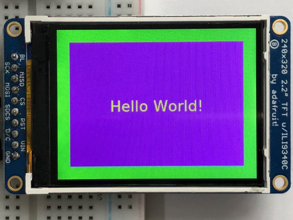
接下来,就像前面的例子一样,我们将设置显示,设置旋转,并创建一个绘图对象。如果您使用的显示器与ILI9341不同,请按照前面的示例调整您的初始化器。之后,我们将用占据整个屏幕的绿色矩形来设置背景。为了得到绿色,我们传入一个元组,元组中有红色、绿色和蓝色的颜色值,顺序可以是 0 到 255之间的任何整数。
- draw.rectangle((0, 0, width, height), fill=(0, 255, 0))
- disp.image(image)
接下来我们将画一个内部的紫色矩形。这与displayio quickstart中的示例颜色值相同,只是十六进制值已转换为十进制值。我们使用BORDER参数来计算我们想要绘制矩形的大小和位置。
- draw.rectangle((BORDER, BORDER, width - BORDER - 1, height - BORDER - 1),
- fill=(170, 0, 136))
接下来我们将加载一个TTF字体。DejaVuSans.ttf字体应该预加载到您的Pi代码中的位置。我们还利用了前面讨论过的font size参数。
- # Load a TTF Font
- font = ImageFont.truetype('/usr/share/fonts/truetype/dejavu/DejaVuSans.ttf', FONTSIZE)
现在我们将文本Hello World绘制到显示屏的中心。您可能会认识到居中计算与我们在前面的示例中用于居中裁剪图像的计算是相同的。在这个例子中,我们使用字体对象的 getsize() 函数获得字体大小值
- # Draw Some Text
- text = "Hello World!"
- (font_width, font_height) = font.getsize(text)
- draw.text((width//2 - font_width//2, height//2 - font_height//2),
- text, font=font, fill=(255, 255, 0))
最后,就像以前一样,我们显示图像。
- disp.image(image)
- """
- This will show some Linux Statistics on the attached display. Be sure to adjust
- to the display you have connected. Be sure to check the learn guides for more
- usage information.
- This example is for use on (Linux) computers that are using CPython with
- Adafruit Blinka to support CircuitPython libraries. CircuitPython does
- not support PIL/pillow (python imaging library)!
- """
- import time
- import subprocess
- import digitalio
- import board
- from PIL import Image, ImageDraw, ImageFont
- import adafruit_rgb_display.ili9341 as ili9341
- import adafruit_rgb_display.st7789 as st7789 # pylint: disable=unused-import
- import adafruit_rgb_display.hx8357 as hx8357 # pylint: disable=unused-import
- import adafruit_rgb_display.st7735 as st7735 # pylint: disable=unused-import
- import adafruit_rgb_display.ssd1351 as ssd1351 # pylint: disable=unused-import
- import adafruit_rgb_display.ssd1331 as ssd1331 # pylint: disable=unused-import
- # Configuration for CS and DC pins (these are PiTFT defaults):
- cs_pin = digitalio.DigitalInOut(board.CE0)
- dc_pin = digitalio.DigitalInOut(board.D25)
- reset_pin = digitalio.DigitalInOut(board.D24)
- # Config for display baudrate (default max is 24mhz):
- BAUDRATE = 24000000
- # Setup SPI bus using hardware SPI:
- spi = board.SPI()
- # pylint: disable=line-too-long
- # Create the display:
- # disp = st7789.ST7789(spi, rotation=90, # 2.0" ST7789
- # disp = st7789.ST7789(spi, height=240, y_offset=80, rotation=180, # 1.3", 1.54" ST7789
- # disp = st7789.ST7789(spi, rotation=90, width=135, height=240, x_offset=53, y_offset=40, # 1.14" ST7789
- # disp = hx8357.HX8357(spi, rotation=180, # 3.5" HX8357
- # disp = st7735.ST7735R(spi, rotation=90, # 1.8" ST7735R
- # disp = st7735.ST7735R(spi, rotation=270, height=128, x_offset=2, y_offset=3, # 1.44" ST7735R
- # disp = st7735.ST7735R(spi, rotation=90, bgr=True, # 0.96" MiniTFT ST7735R
- # disp = ssd1351.SSD1351(spi, rotation=180, # 1.5" SSD1351
- # disp = ssd1351.SSD1351(spi, height=96, y_offset=32, rotation=180, # 1.27" SSD1351
- # disp = ssd1331.SSD1331(spi, rotation=180, # 0.96" SSD1331
- disp = ili9341.ILI9341(
- spi,
- rotation=90, # 2.2", 2.4", 2.8", 3.2" ILI9341
- cs=cs_pin,
- dc=dc_pin,
- rst=reset_pin,
- baudrate=BAUDRATE,
- )
- # pylint: enable=line-too-long
- # Create blank image for drawing.
- # Make sure to create image with mode 'RGB' for full color.
- if disp.rotation % 180 == 90:
- height = disp.width # we swap height/width to rotate it to landscape!
- width = disp.height
- else:
- width = disp.width # we swap height/width to rotate it to landscape!
- height = disp.height
- image = Image.new("RGB", (width, height))
- # Get drawing object to draw on image.
- draw = ImageDraw.Draw(image)
- # Draw a black filled box to clear the image.
- draw.rectangle((0, 0, width, height), outline=0, fill=(0, 0, 0))
- disp.image(image)
- # First define some constants to allow easy positioning of text.
- padding = -2
- x = 0
- # Load a TTF font. Make sure the .ttf font file is in the
- # same directory as the python script!
- # Some other nice fonts to try: http://www.dafont.com/bitmap.php
- font = ImageFont.truetype("/usr/share/fonts/truetype/dejavu/DejaVuSans.ttf", 24)
- while True:
- # Draw a black filled box to clear the image.
- draw.rectangle((0, 0, width, height), outline=0, fill=0)
- # Shell scripts for system monitoring from here:
- # https://unix.stackexchange.com/questions/119126/command-to-display-memory-usage-disk-usage-and-cpu-load
- cmd = "hostname -I | cut -d' ' -f1"
- IP = "IP: " + subprocess.check_output(cmd, shell=True).decode("utf-8")
- cmd = "top -bn1 | grep load | awk '{printf \"CPU Load: %.2f\", $(NF-2)}'"
- CPU = subprocess.check_output(cmd, shell=True).decode("utf-8")
- cmd = "free -m | awk 'NR==2{printf \"Mem: %s/%s MB %.2f%%\", $3,$2,$3*100/$2 }'"
- MemUsage = subprocess.check_output(cmd, shell=True).decode("utf-8")
- cmd = 'df -h | awk \'$NF=="/"{printf "Disk: %d/%d GB %s", $3,$2,$5}\''
- Disk = subprocess.check_output(cmd, shell=True).decode("utf-8")
- cmd = "cat /sys/class/thermal/thermal_zone0/temp | awk '{printf \"CPU Temp: %.1f C\", $(NF-0) / 1000}'" # pylint: disable=line-too-long
- Temp = subprocess.check_output(cmd, shell=True).decode("utf-8")
- # Write four lines of text.
- y = padding
- draw.text((x, y), IP, font=font, fill="#FFFFFF")
- y += font.getsize(IP)[1]
- draw.text((x, y), CPU, font=font, fill="#FFFF00")
- y += font.getsize(CPU)[1]
- draw.text((x, y), MemUsage, font=font, fill="#00FF00")
- y += font.getsize(MemUsage)[1]
- draw.text((x, y), Disk, font=font, fill="#0000FF")
- y += font.getsize(Disk)[1]
- draw.text((x, y), Temp, font=font, fill="#FF00FF")
- # Display image.
- disp.image(image)
- time.sleep(0.1)
- import time
- import subprocess
- import digitalio
- import board
- from PIL import Image, ImageDraw, ImageFont
- import adafruit_rgb_display.ili9341 as ili9341
接下来,就像前两个例子一样,我们将设置显示,设置旋转,并创建一个绘图对象。如果您使用的显示器与ILI9341不同,请按照前面的示例调整您的初始化器。
就像第一个例子一样,我们要画一个黑色的矩形来填满屏幕。之后,我们将设置几个常量来帮助定位文本。第一个是填充,这将是最上面文本的Y位置,另一个是X,这是X位置,代表文本的左侧。
- # First define some constants to allow easy positioning of text.
- padding = -2
- x = 0
接下来,我们像第二个例子一样加载一个字体。
- font = ImageFont.truetype('/usr/share/fonts/truetype/dejavu/DejaVuSans.ttf', 24)
现在我们进入主循环,通过使用while True:,它将循环直到在键盘上按下Control+C。这里的第一项,我们清空了屏幕,但是请注意,我们没有像以前那样给它一个元组,我们只需传递0,它就会变成黑色。
- draw.rectangle((0, 0, width, height), outline=0, fill=0)
接下来,我们使用子过程函数运行一些脚本,这些函数被操作系统调用以获取信息。每个命令中的都通过awk传递,以便更好地格式化显示。通过让操作系统来完成这项工作,我们不必这样做。这些小脚本来自 https://unix.stackexchange.com/questions/119126/command-to-display-memory-usage-disk-usage-and-cpu-load
- cmd = "hostname -I | cut -d\' \' -f1"
- IP = "IP: "+subprocess.check_output(cmd, shell=True).decode("utf-8")
- cmd = "top -bn1 | grep load | awk '{printf \"CPU Load: %.2f\", $(NF-2)}'"
- CPU = subprocess.check_output(cmd, shell=True).decode("utf-8")
- cmd = "free -m | awk 'NR==2{printf \"Mem: %s/%s MB %.2f%%\", $3,$2,$3*100/$2 }'"
- MemUsage = subprocess.check_output(cmd, shell=True).decode("utf-8")
- cmd = "df -h | awk '$NF==\"/\"{printf \"Disk: %d/%d GB %s\", $3,$2,$5}'"
- Disk = subprocess.check_output(cmd, shell=True).decode("utf-8")
- cmd = "cat /sys/class/thermal/thermal_zone0/temp | awk \'{printf \"CPU Temp: %.1f C\", $(NF-0) / 1000}\'" # pylint: disable=line-too-long
- Temp = subprocess.check_output(cmd, shell=True).decode("utf-8")
现在我们为用户显示信息。这里我们使用另一种方式来传递颜色信息。我们可以使用磅符号将它作为一个颜色字符串传递,就像我们在HTML中所做的那样。对于每一行,我们使用getsize()获取该行的高度,并将指针向下移动那么多。
- y = padding
- draw.text((x, y), IP, font=font, fill="#FFFFFF")
- y += font.getsize(IP)[1]
- draw.text((x, y), CPU, font=font, fill="#FFFF00")
- y += font.getsize(CPU)[1]
- draw.text((x, y), MemUsage, font=font, fill="#00FF00")
- y += font.getsize(MemUsage)[1]
- draw.text((x, y), Disk, font=font, fill="#0000FF")
- y += font.getsize(Disk)[1]
- draw.text((x, y), Temp, font=font, fill="#FF00FF")
最后,我们使用disp.image()将所有信息写入显示器。既然是循环,我们就告诉Python睡眠0.1秒,这样CPU永远不会太忙。
- disp.image(image)
- time.sleep(.1)
